MEMBRANES, MOLECULES AND THE SCIENCE OF PERMEATIONPage 2 Measuring evaporative vapor emissionsUsing its ''evaporative loss model,'' ARID has estimated the magnitude of the evaporative vapor emissions and associated reductions in the overall efficiency of vapor recovery under each of four possible refueling scenarios described above. These estimates are shown in Table 1, below. The key inputs in the model are gasoline Reid Vapor Pressure (RVP), the storage tank temperature and the air ingestion volume or vapor to liquid ratio (V/L). The data on total emissions and recovery percentages (far right two columns) are applicable only if the systems are not equipped with vent vapor processing units. With reference to Table 1, note the range of evaporative emissions for a dispensing facility that pumps 100,000 gallons of gasoline per month: from 0.92 to 10.76 tons per year. Also note that the uncontrolled refueling emissions for this same facility are estimated at 5.04 tons per year. Therefore, depending on the V/L, RVP and storage tank temperature, the evaporative emissions can exceed the uncontrolled refueling emissions by up to a factor of two. If one considers a centralized vacuum-assist system operating at V/L of 2.0, the evaporative losses can exceed the uncontrolled refueling losses by up to a factor of three. For a central vacuum system, the resulting large losses are combusted and do not result in atmospheric emissions. However, the economic value of the combusted material is lost. Also, the generation of combustion by-products, such as carbon dioxide and oxides of nitrogen, contribute to the formation of undesirable ''greenhouse'' gases. Also as seen in Table 1 below, the storage tank evaporative emissions exceed the "uncaptured" refueling emissions for every scenario except the uncontrolled, first case (no Stage II and no ORVR). Even if Stage II and ORVR systems are 95 percent efficient in capturing refueling losses, the evaporative losses from the storage tank significantly reduce the capture efficiency of the refueling emissions. It is important to note that all of the overall recovery efficiency values are well below the 95 percent minimum required by the Clean Air Act Amendments of 1990 for Stage II systems. Moreover, even if 100 percent of vehicles on the road had ORVR systems, the best overall recovery efficiency one can hope to achieve, without using a vent vapor processor, is only 50 percent ([9.48-4.69]) ÷ 9.48). One such processor involves the use of a membrane system to separate, concentrate and recover hydrocarbons from air/vapor mixtures. Such a system can significantly reduce evaporative vapor emissions, which, as discussed above, are becoming more significant as the population of ORVR-equipped vehicles increases.
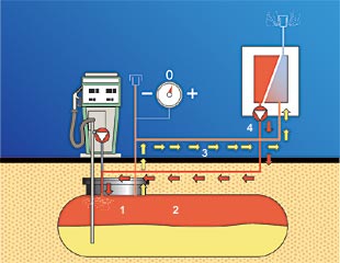
Membrane vapor processing technologyWorking with a leading European research institute, ARID Technologies has designed a vapor recovery system for gasoline storage tanks using a "selectively permeable" membrane. The membrane technology has been proven to be effective over many years in large storage tanks at bulk plants and refineries. ARID has simplified this technology for the retail service station environment. This system, called PERMEATOR, separates hydrocarbon vapors from air; exhausts the cleaned air to the atmosphere; and returns the enriched hydrocarbon vapors to the storage tank head space. By selectively removing air from the storage tank head space, storage tank pressures are reduced and fugitive and vent emissions are virtually eliminated. The system is installed on manifolded tank vent lines. It can be used at uncontrolled stations (no Stage II) as well as Stage II-compliant facilities using balance or vacuum-assist (dispenser based and centralized) vapor recovery systems. The selectively permeable membrane material is positioned in a compact module that exhibits very low pressure drop and excellent mass transfer characteristics. The entire system is housed in a relatively small enclosure (measuring four feet W x two feet H x two feet D) that can typically be installed without any excavation. Energy consumption is minimized since all streams enter and exit the membrane in vapor phase. Normal operation of the vent lines is not impeded because the system is installed parallel to the vents. No restriction whatsoever is created in the vapor pathway. Six PERMEATOR systems are currently in operation (one in the US and the others overseas) as part of test programs. The units are being monitored to verify ARID's projected overall estimates of vapor recovery efficiency of 95 percent.
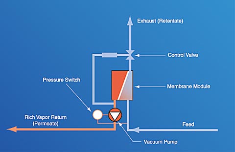
Note: As tank pressure decreases to a pre-set level, the pressure switch automatically deactivates the PERMEATOR system. How the membrane worksFig 2: How the Membrane Works The membrane is made of extremely thin, selectively permeable, polymeric films attached to a porous support structure. Membrane films are integrated into modules to provide maximum surface area per unit volume of pressure housing. Unlike conventional particle filters that separate materials based on physical size differences, the membranes used by ARID separate compounds based on differences in the solubility and diffusivity of specific molecules. Hydrocarbon molecules pass through, or permeate, the thin polymer film more rapidly than other molecules and are returned to the storage tank (see Figures 1 and 2). Molecules such as oxygen and nitrogen (air) are much slower permeators, and they are "rejected" by the membrane film and vented to the atmosphere. The difference in permeation rates between hydrocarbon and air molecules allows for separation of gasoline vapors from air. The system operating cycle is described and illustrated in Figure 2 at right.
Membranes article continued |
video-flash-img-content


